The Val Ease Central Railroad ©
Taking Z Scale to the Public Around the World
(Text and photos © Copyright Jeffrey MacHan)
Howard Kannitbee, P.E., Superintendant of Engineering, VECRR
Construction Diary - Opening "Val Ease Summit"
VES Construction, part 8: Shortinndi Wyring's Guide to VES hookups
Things had been going so good during VES construction that it was just a matter of time before something went wrong. As could be expected, "wiring the wye", the least complicated stage of construction, is where it happened.
Even the best laid layout building plans can go awry but I think it's only fair to share what the problem was, where it came from and how it was corrected. In order to do so, we must go back to the beginning...
Reverse loop, anyone?
From the earliest design stages for VES a return loop in the form of a "wye" had figured into the track plan. I wanted an "unusual" trackplan element to add variety and operational interest to VES. This was especially challenging considering the very small space within which the "wye" had to fit. On the drawing board it was easy to concoct various "wye" configurations, one with a double mainline, one with a single reverse lead and a parallel siding, one with a team track, etc. In all of the theoretical designs the "wye" lead had room for a locomotive and three cars. This "planning" exercise did not stand up well when confronted with the physical restrictions of reality!
When the time came to actually lay out track components, the design process started all over again. Theory went out the window and "hands-on" fitting of set track pieces of different radii and LH / RH / straight / curved turnouts once again became my planning method of choice. It took some fiddling and it took some time but I finally reached a reasonable compromise at the very last moment. The final track plan did save the "wye" but only because of a double-slip switch. Without it, there was simply not enough room to make the design work. The compromise in question is the fact that each "wye" lead is only long enough to hold two 50' freight cars or one F7 loco (or something shorter) and a 50' freight car. Each side of the "wye" has room for three 50' freight cars while the "base" or mainline side of the "wye can hold four 50' cars. From an operational standpoint, this is just long enough to actually turn a locomotive around a seven car train with a little bit of fancy manouvering.
If you build it, ya gotta wire it, too!
Reverse loop wiring can sometimes be confusing. It had been a few years, nay, quite a few years, since I had wired a reverse loop. Sure I had installed the turntable which is technically a reversing section but I solved the problem by powering the bridge from the stub track leads which effectively eliminated the reverse loop all together. When the time came to wire the "wye", I didn't trust myself to simply attach wires and cut gaps from memory. I did recall that I did need to attach wires and cut gaps, still pretty good for someone of my vintage. Not being averse to doing research, I checked the NMRA web site for the "Beginner's Corner" area where, lo and behold, there was a simple description of a "wye" and its wiring requirements. Not a problem, I thought.
The NMRA wiring diagram shows gaps cut in one arm of the "wye" between the two facing turnouts. In theory, this reversing block could be any length, from one engine to an entire train. At first glance, I didn't notice any problem at all with this block division scheme. So, I put on my safety glasses, loaded up the cutting disk in my rotary tool, plugged it it and cranked it up. Five minutes later I had four nice cuts in my rails and I was ready to solder the leads. Once that had been done, I wired a DPDT center-off sub-miniature toggle switch as a reversing switch and attached the leads from the mainline and the "wye" block. It was time!
|
Making Connections
Jeffrey MacHan Note: The soldering techniques used on VES are traditional and nothing out of the ordinary. I simply thought that I'd show you what was done as a tribute to Shortinndi Wyring's philosophy..."If it was worth doing right in the first place, someone else would have done it!"
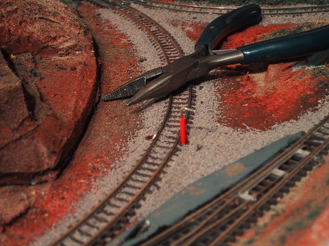 Wiring the "wye" reversing block: the holes have been punched through the foam, the straws inserted and the wires tinned and tips bent. I placed a little dab of liquid flux on the side of the rail and held the wire in position using a pair of snub-nosed hobby pliers. Using a pre-tinned soldering iron the joint was made rapidly. The pliers acted as a heat sink.
 The reversing toggle switch wires to the mainline were soldered to the tabs of the Märklin feeder track which was conveniently hidden behind a rock outcropping. The capacitor between the tabs was removed.
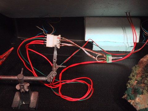 The four wires from the the track (two from the mainline and two from the reverse block) were soldered onto the pins of an automobile safety connector. The other half of the connector runs wires to the DPDT reversing toggle switch seen to the right of the connectors.
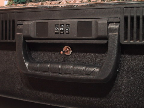 After a quick look around the suitcase it was decided that the best place for the "wye" reversing switch was at the front of the case, neatly tucked under the combination lock and somewhat hidden by the handle. It would be too much to hope for to expect that certain short "passengers" would not discover the switch during operating hours...and I better have a good explanation to give to customs agents at international border checkpoints!
|
Let's take the VES for a test drive!
The moment of truth had arrived. I was mainly concerned with dirty track at this point. I placed a trusty F7 on the rails, hooked up the DC output from an MRC1300 to the mainline using aligator clips. Things did not go quite as planned!
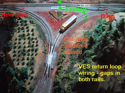
The old gap placement caused operating problems that were solved when the gaps were moved to the left hand side of the "wye". The "feeders" connect to the DPDT center-off toggle switch. The DPDT reverses the polarity in the reversing block and can turn off the current if a parking spot for motive power is needed.
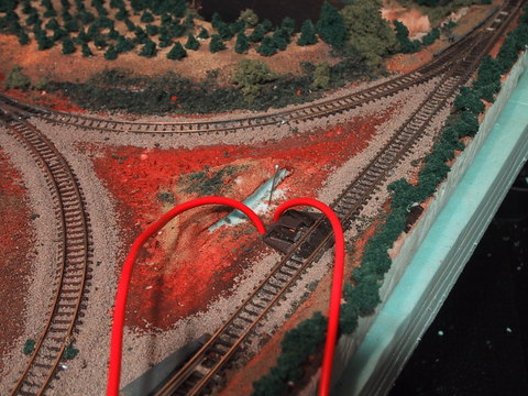
Notice on the above diagram where the original gaps were cut in the Right hand side of the "wye" between the curved turnout and the double slip. Imagine the locomotive entering the "wye" from the Right and entering the reversing block in the same direction of travel. If the locomotive continues out of the block it would cause a short as soon as it crossed the gap nearest the double slip. This is because the mainline polarity is effectively reversed at the point where the reversing block encounters the bottom point of the "wye". In order to continue out of the wye and turn the loco it would be necessary to...
- stop the locomotive inside the reversing block (position seen in the photo),
- reverse the mainline direction on the MRC1300 throttle (NOTE: this also reverses the return loop block direction),
- reverse the direction of travel of the reverse loop block using the DPDT toggle switch newly installed in the front of the case,
- then run the locomotive out of the reversing block onto the "wye" and past the double slip switch,
- then finally change the direction of the mainline at the MRC1300 throttle, align the double slip and the mainline switch to take the opposite leg of the "wye" and drive the locomotive out onto the mainline.
This is definitely TOO much WORK! There had to be an easier way and there was.
I took my liquid flux, soldering iron and safety glasses and went to work filling in the two gaps closest to the double slip as shown on the diagram. Then I fired up my rotary cutting tool and cut two new gaps in the "wye" leg opposite the first set of gaps. Notice that the "new" gaps actually create a reversing block that is in the shape of a "Y". Cool!
So what difference does this make in running a loco through the "wye"? Let's take a look at the steps involved.
- enter the reversing block from the mainline and run the loco past the double slip,
- change the direction of the reversing block using the DPDT toggle switch,
- align the double slip and the mainline switch to take the opposite leg of the "wye" and drive the locomotive out onto the mainline.
That's the way it was supposed to work the first time. No need to change mainline polarity. Even Shortinndi Wyring* would be proud. Sweet!
Once VES is hooked up next to CVE, mailine power will be supplied via the track connectors to CVE. Mainline control will be handled by the CVE throttle when the outside loop is switched to CVE or the VEW throttle when the outside loop block is switched to local VEW control. The direction of travel in the "wye" will be controlled by the front DPDT centre-off toggle switch. The "wye" is also a holding block for a switcher.
Come to think of it, at some point I'll have to ask Shortinndi Wyring how the VECRR throttles and control divisions are wired. I'm sure he'll tell us more than we ever wanted to know!
A Shortinndi Wyring KISS tip: An "simple" way to check reversing loop polarity is to draw a diagram showing both rails. Then place a coin on both rails on the diagram (heads on one rail, tails on the other) inside the loop or "wye" reversing block as in this case. Take two other coins and place them next to the first pair of coins with their faces the same way up as their neighbour on the same rail. Then slide the two travelling mainline coins along the tracks with your fingers. Follow the rails all around the track and through the "wye" until they meet their neighbours on the reverse side. See how the coins now show opposite faces to their neighbours on the same track. Of course you can do the same thing using + and - signs but I like to use props, they don't leave smudges on the diagram. ;-)
*Biographical tidbit: VECRR Chief electrician, charter member of the Val Ease Model Railroad Club and champion yodeller. (Rumour has it that Shordinndi took up yodelling as a natural extension of the screams he would regularly emit when handling live wires on the job).