The Val Ease Central Railroad ©
Taking Z Scale to the Public Around the World
(Text and photos © Copyright Jeffrey MacHan)
Wired for FUN – Power and Controls for the VECRR
Most model railroaders put most of their time and effort into track planning, scenery design, roster development, construction and basic control wiring. In the case of the VEC, I spent most of my time designing the electrical and control systems needed to “reliably” run one or more trains on trackage that would take a beating inside one, then two, then three, and why not, four 30” x 22” hard-side suitcases.
Design Considerations and Goals
I believe that a “successful” model railroad (one that gives years of pleasure to its owner) is as much the result of initial planning than its skillful construction. It took me four months to build the first division of which three months went into thinking about my goals for the layout and how to achieve them.
In addition to era, geography, and track plans, I spent a good deal of time working on my wants and needs in terms of control systems. Here are some of the design goals, many of which forced me to come up with some quite original solutions.
- a “real” layout, i.e. switching operations, lighting and other electronic effects.
- the same reliability that I was accustomed to with my N-scale layout.
- no custom-built power throttle or battery power for my suitcase empire. If possible, my design goal was to use off-the-shelf power such as the MRC 1300 throttle (listed as Z-safe by Micro-Trains Line).
- synchronized sound using an MRC 7000 sound generator (diesel horn, motor / steam chuff, whistle).
- hand-held controls.
- a diode-matrix power routing scheme and a CDU (capacitor discharge unit) to activate all of my turnout motors.
- a Relco hi-frequency track conditioner.
- a voltmeter / ammeter.
- packable inside the suitcase for easy transportation.
- Above all, I wanted to have a layout that would be FUN to build, run and share.
Easier said than done!
My previous N-scale empire was powered from a free-standing consol / control panel that was connected to the layout using 6 foot-long computer ribbon connector strips. Based on that experience, I knew that I could reliably power my Z layout using an RS232 cable which uses the same 24-gauge copper wires as the ribbon cables. A hunting expedition to my local electronics supply store turned up a 5” x 3” x 2.5” plastic project box that offered consol-bashing potential.
There is nothing I enjoy more than to find an original way to solve a problem and packing everything that I wanted into a small, hand-holdable package was quite a challenge, indeed. The key to my success was to “divide and conquer”. Once I had collected all of the necessary components, I needed to do some planning in order to put the bare minimum inside the control box and to maximize use of the 25 conductors, 26 if you use the foil ground wrapper (which I did), found in an RS232 cable.
My first step was to separate the low-voltage electronics (Darlington power transistor and throttle components) from the high-voltage step-down transformer contained in the MRC 1300 enclosure. I used a metal-cutting blade in a hacksaw to slice open the MRC1300 case along the shell seam and then removed the electronics leaving the transformer in place. NOTE: I have also used the components from MRC 1400 and 2800 throttles (no pulse power electronics that are dangerous to fragile Z motors).
Another key to my success was to document everything. All the wires were labeled, all the pin outs were identified with their number and purpose. I maintained a full schematic diagram of the electronics and the power connections. NOTE: these diagrams served me very well when it came to trouble-shoot the system. I also provided the schematics as part of my NMRA – Model Railroad Engineer – Electrical certificate requirements.
Mains power supply
110v AC is supplied to each suitcase of the VEC using a standard computer power cord and receptacle. The receptacles are neatly cut into the side of the Delsey hard-side suitcases inside the retractable handle area. The area is flat and big enough to give me room for the AC receptacle as well as a female 25-pin RS232 plug, a miniature 1/8” jack for outside low-voltage AC power and a single-pole single-throw slide switch to cut power to the Relco high-frequency track conditioner. I made a template for these connectors so that all four VEC cases have identical openings. It all looks very high tech and professional.
I hard-wired the electrical cord from the MRC power pack to the 110v receptacle and protected the solder joints with heat-shrink tubing and electrical tape. The MRC shell was “velcroed” into place in the back left-hand corner of the suitcase. Both the 12v AC and 16v DC taps were used to supply current to the electronics that I transferred to the plastic project box that would become the hand-held throttle / control panel.
NOTE: working with 110v mains wiring presents a potentially fatal shock hazard and should not be attempted by anyone without adequate electricity training and safety knowledge.
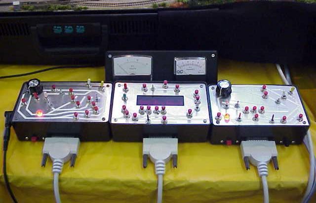
A picture is worth several thousand words: from left to right - VEE local cab (throttle and sound), CVE tower (switching and fast clock), VEW local cab (throttle and sound), voltmeter / ammeter consol (plugged into VEE cab on the left). Sound selection (diesel / steam), volume, engine revs / chuff rate and whistle / horn blasts are controlled using slide switches, potentiometers, and two-tone slide control, all removed from an MRC 7000 sound generator. If there are enough wires available, certain accessories are activated using the slide switches seen on the bottom of the control boxes.
Single-cab “tower” control for 3-train operation
Low-voltage AC – DC power is supplied via 10'-long 25-conductor RS232 cables. The limited number of wires available in an RS232 cable basically forced me to adopt a single-cab design for the VEC. A dual-cab design could have been developed using a 40-conductor or larger cable. I did look into the potential of a larger cable but I found them to be too thick, too heavy, not very flexible and much too expensive for my tastes. Single-cab wiring uses a common return that freed up a few extra conductors for other applications.
Each of the three VEC control panel boxes can be thought of as “Tower” cabs where the operator has control of a VEC division from a “tower”. The VEC allows a single train to run over the trackage governed by each “tower”.
Val Ease East
VEE has the most complicated wiring of the layout. The suitcase houses a turntable, motorized roundhouse, 9 motorized turnouts, 10 streetlights and arc welding unit, Relco hi-frequency track conditioner, a CDU and a sound effects tape player. The cab houses the MRC 1300 transistor throttle, the MRC 7000 sound equipment, and a meter plug along with 10 route-selection push buttons, 4 block power toggles, DPDT direction toggle and one accessory switch. VEE is a single-cab configuration designed for one-train-only operation although a second train can be run over the outside mainline from the “third cab”. Blocks are controlled using sub-miniature single-pole single throw (SPST) toggle switches.
Val Ease West
VEW was the first section of the VEC and is the place where I made most of my mistakes, sorry, discoveries. The suitcase houses 7 motorized turnouts, 9 streetlights, a Relco hi-frequency track conditioner, a CDU, a sound effects tape player and a tiny FM radio. The cab houses the MRC 1300 transistor throttle, the MRC 7000 sound equipment, and a meter plug along with 9 route-selection push buttons, 5 block power toggles, DPDT direction toggle and one accessory switch.
Centre Val Ease
CVE tower control does not have an integrated throttle since track power comes from the “third cab”, a tethered hand-held transistor throttle. Since CVE has a classification yard and numerous sidings, there are 14 route-selection push buttons. CVE only boasts 3 blocks which are powered by SPST toggle switches. Instead of a throttle, there was space in the control box for an 8x digital “fast” clock. I cut a rectangle in the aluminum face plate for the electronic display and I used a combination of SPST and DPDT toggle switches to set the clock TIME plus RUN and HOLD. The 8x fast clock compresses a 24-hour timetable into an 3-hour operating session for up to 3 operators plus a dispatcher.
The “third cab”
The hardest part about adding CVE to the VEC was designing a throttle and block control system that would allow an operator to run a train completely around the layout on the outside main line and to do switching on CVE. The solution was to separate the throttle from the control box and to rewire the outside mainline loop as a dual-cab block.
The outside mainline loop on both VEE and VEW is a “common” block that is a specially wired dual-cab block using a 3-position double-pole double-throw (DPDT) center-off sub-miniature toggle switch. The three positions are “local cab” control, power off and “third cab” control.
When the toggle is set to “local” the local cab provides power to the block. When off, the block is used to hold a train according to the operating timetable. When “shared”, control of the outside loop is switched to the third cab, a 15' tethered hand-held throttle (pictured in the hands of Helmut Paule). The third cab controls trains in CVE and around the outside loop when the block selector is set to “third cab” position. I purposely designed the throttle to be light, robust, easy to hold and operate using a large speed control knob (and not much else) so that kids could enjoy running a train around the outside main line at train shows without danger of causing crashes and collisions.
The single-cab throttle is hard-wired to a distribution box via a 15-foot long, 6-conductor telephone cable. The throttle is a Darlington power transistor originally from an MRC 1400 unit. A .5-amp 16-volt DC wall adaptor scavenged from an old slot-car set provides enough power to run a double-headed engine consist as well as for the limited lighting effects found on the bridging section between VEE and CVE (campfire and 1 streetlight). The distribution box provides track-power leads that plug into quick-release plugs wired to the VEE-upper CVE bridge track section.
Turnout diode-matrix route selection
In order to minimize the number of wires needed to control turnout motors (all my turnouts are motorized and connected to a transistorized CDU), I used momentary-on push buttons positioned on the track plan to optimize route selection. Routes include single sidings and branch lines (from 1 to 4 turnouts), multiple crossovers (from 2 to 4 turnouts) and mainline reset (up to 5 turnouts). A Capacitor Discharge Unit is an absolute must for solenoid-powered turnouts. A CDU provides a very short-duration, high voltage discharge which activates the solenoids used on Marklin motors. The charging transistor recycles the CDU in less than a second so that I can punch buttons all day long without having to wait for the capacitor to recharge.
Diodes are used to prevent sending power to the “wrong” solenoids in a route-based design. Each route is plotted on my switching diagram and the diodes are wired to the turnout leads under the layout base, not inside the control box. All routes were tested individually as work progressed and, yes, I did make mistakes and I have come across the rare bad diode. That is part of the learning process. However, once the routes worked, they have worked ever since (going on 15 years for Val Ease East).
MRC 7000 sound generators
Another fun sub-project was to add synchronized sound to the power cabs. I cut up an MRC 7000 (US-style) sound generator and transferred all of the components into the control box. I had to do some printed circuit board surgery in order to make everything fit (wish I had used a slightly bigger project box!) but I did manage to squeeze in all of the parts. I had to insulate the PCB board to prevent it from shorting out the turnout push buttons. I also had to bend the push button leads to the side to free up as much space as possible. The Darlington power transistor was positioned along the bottom surface of the box in order to find room for its attached heat sink. I still think that this packing job is one of my finest ever!
Voltmeter / ammeter
The NMRA Model Railroad Engineer – Electrical certificate requires meters. My solution for the VEC was to build a plug-in meter set that would normally be used when trouble-shooting locomotive performance. Housed in a low-profile plastic electronics project box, the voltmeter / ammeter combination plugs into the outside of the two single-cab throttles (VEE and VEW) using a 4-conductor cable with 1/8” stereo phono jacks. Meter readings measure the load of the connected cab. The real challenge to this sub-project was to find meters with fine-enough measurement ranges (0 – 15 volts and current in milli-amps).
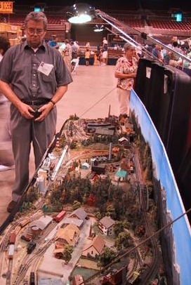
Helmut Paule, holding the tethered third cab (speed, direction, power indication diode, three-position accessory switch), follows his ICE train as it speeds around the outside loop on the VEC.
Lighting, smoke, turntable and other accessories
In order to keep various power systems separate, I powered the low-voltage streetlights, smoke generators, flashers, tape players, fast clock etc. using a selectable-voltage wall-transformer in each suitcase. I used both 3-volt and 9-volt power sources depending on the need. I used 12-volt grain-of-rice lamps wired in series (3 lamps) connected to a 9-volt source in order to prolong bulb operating life. Where applicable, I used red LEDs for accent lighting. All of these power supplies are plugged into a multi-plug AC power bar, always equipped with quick-action short circuit protection.
Background sound effects are provided by a 3-volt cassette tape player in each suitcase. VEE plays a medley of industrial sounds. CVE plays seagulls screeching, VEW offers several farm animals (cows, sheep) as well as a waterfall effect generated by a very small and cheap FM radio tuned to static and plugged into a small speaker placed near the falls under the layout. All of these electrical components are neatly arranged and semi-permanently mounted inside the suitcase.
The VEC is equipped with two Seuthe smoke generators ( one each in VEE and CVE) running off of a 6-volt supply. Each smoke generator has an ON-OFF toggle switch hidden near by to power them up only when needed.
VEE is home to a Märklin turntable that is powered with 6 volts in order to keep the motor whine to an acceptable level. I rewired the controls so that I could use a sub-miniature DPDT spring-loaded center-off toggle switch for turntable direction and rotation. I also installed the solenoid-powered roundhouse doors but used a SPST spring-loaded center-off sub-miniature toggle switch to open and close the doors. NOTE: a more detailed presentation of the VEC turntable wiring solution was published in the May-June 2001 issue of Ztrack Magazine (back issues are available from Ztrack). Members of VECRR Yahoogroup have access to this and dozens of other articles in the Val Ease County Library. New members are always welcome. See www.Val-Ease-Central.com for directions.
Conclusion
Several years into my VEC train show adventures I was informed by an electrical engineer that the wire gauge of an RS232 would not work to power a Z layout, too much voltage drop. Good thing I found this out after I had finished wiring the VEC, otherwise I might never have taken the Z plunge and I would not be writing “Last Spikes”. Still, I agree that using the largest wire gauge possible is definitely desirable and that learning how to make good solder joints is an absolute must for “electrically reliable” layout operations. You and I want to run trains, not hunt down electrical gremlins.
For me, much of the joy of Z-scale model railroading is the result of having to devise unique and sometimes original solutions to self-imposed space considerations. Model railroading is as much art as craft and occasionally it is possible to do the “impossible” by using one's imagination and creativity.
One last thing, electronics and electricity follow strict rules and do not take kindly to improvisation. Learn how to safely handle electricity and document everything you do, you will be glad you did.